Technologies for Transmission System
Current advances in technology offer project promoters many opportunities to implement new solutions to cope with future network development, which is defined in the TYNDP. Together with current technologies, innovative technologies will be incorporated with the existing infrastructure. These technologies have their own learning curves and innovation cycles. Project promotors, regulators and policy makers need to understand something of each technology and their availability by the time of project development.
This text on technologies for transmission systems is co-authored by ENTSO-E, Europacable, Friends of the Supergrid, Orgalime and T&D Europe.
The projects in the TYNDP comprise of alternating and direct current technologies, overhead lines as well as onshore and offshore cables. Therefore, technologies for future network development can be grouped as follows:
- High voltage alternating current (HVAC) power technologies
- High voltage direct current (HVDC) power technologies
- Hybrid HVAC/HVDC power technologies
This report seeks to provide an assessment of transmission technologies available today and project their availabilities beyond the next ten years, to 2030. Main reference of this report are several deliverables on technologies of the e-Highway2050 project, which readers are strongly suggested to read for detailed information.
The report focuses on illustrating the availability of technologies and the time by which they might be in service. It provides a high-level view of a technology spectrum for project promotors to select and investigate further technologies that could best suit their projects.
HVAC Power Technologies
Overhead Lines
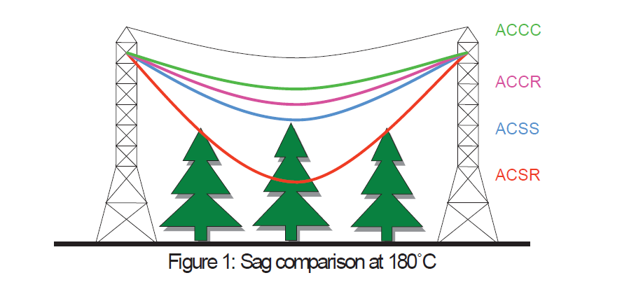
Overhead lines (OHL) have been widely used in transmission networks for over one hundred years. However, there are new conductors available carrying higher currents, while allowing higher temperature ratings. Those conductors, such as Aluminium Conductor Steel Supported (ACSS), Aluminium Conductor Composite Core (ACCC), Aluminium Conductor Composite Reinforced (ACCR) are made of materials with a broader range of arrangement possibilities than conventional Aluminium Conductor Steel Reinforced (ACSR)
By using high temperature conductors (HTC), 30% more capacity and low sag can be achieved (Figure 1). HTC is able to withstand higher operating temperatures, thus carrying a higher amount of power compared to conventional conductors. A lower slag can lead to larger vain, which results in reducing number of towers needed.
HTC costs are generally higher than conventional conductors. However, HTC can enhance (n-1) security reserves and transmission capacity without impacting the negotiated right-of-way, ideally with minor modifications of transmission towers (mostly clamps and mountings). Although existing lines are used, in some countries such projects have to go through the authorization or impact assessment procedure again, especially when magnetic field levels are increased as the expected currents are higher.
Examples of the choice of HTC has been made for several projects of the TYNDP: the 260 km long 400 kV overhead line between France and Italy, the 80 km 400 kV double circuit line between Belgium and France, the ongoing upgrade of a 220 kV line in Poland, and in Belgium the Horta-Mercator and Gramme-Van Eyck lines.
Real Time Thermal Rating (RTTR)
Recently, some smart sensors solutions have been introduced on the market. Those systems bring an assessment of the actual conductor sag by direct physical measurements on the conductors. These devices need however an electrical/mechanical/thermal model of the conductor and meteorological data to assess what is really interesting for the grid operator: The available current margin in the line and so its real-time load transfer capacity. The devices needs also some specific communication facilities to collect all the necessary data.
Some other solutions are also presently on development with a good probability to bring promising results in the next coming years.
The main benefit of real-time thermal rating is the enhancement of (n-1) security reserves, by providing system operators the actual available capacity on the transmission line, while respecting clearance and design limits. The possible gains vary typically between 10 and 30 %. But to be fully operational the RTTR must not only bring a photography of the actual line operating conditions but more importantly to bring reliable information regarding the evolution of these conditions in the next minutes or tens of minutes.
This enhancement of transmission capacity can prevent unnecessary contingency like (n-1) actions. This requires necessarily a modelling of the conductor regarding the weather condition for an adequate forecast in case of an increasing load.
RTTR technology is rather mature, but needs further development to address integration challenges.
HVAC cables
Cable is used as an alternative when overhead line is not appropriate, e.g. in densely populated and reserved areas, across a river or offshore. Another alternative is gas insulated lines, which is included in this category.
These technologies are in service and available (green level).
Onshore cable technology
From an underground cable perspective, HVAC cables are widely used at voltage levels up to a maximum voltage of 550 kV at a global scale. In Europe, currently the maximum voltage is 420 kV. Extruded XLPE insulated cables are the most common, up to 275 kV for over 20 years and cables at 400 kV have been in use over the last 15 years.
Looking at the decades ahead, the concept of partial undergrounding of HVAC transmission lines will be one of the solutions to overcome public acceptance and obtaining building permits. This overall evolution will be enabled by the maturity of XLPE underground HVAC cables and accessories. However, some challenges need to be tackled, e.g. long outage times after damage or failure, transient behavior and reactive power produced by cables. Specific risks for network operation have to be carefully analyzed case by case.
The focus of the technical evolution will be oriented toward the further increase of reliability and the rationalization of future applications:
- The European transmission network voltage is likely to stay in a similar voltage range of 380 – 420 kV and consequently no increase of this voltage level is expected in the future;
- Current rating for a typical partial undergrounding solution (400 kV, 2500 mm2 copper) is expected to increase above 1,8 kA;
- Transmission power of such a system as described above is expected to exceed 1250 MW per circuit.
Some examples:
- TenneT 380 kV AC Randstadt project, The Netherlands: Total length 85km, of which 20km underground (seversal sections, upt to 10 km); Transmission capacity 2x2635 MVA, XLPE cable
- National Grid 400 kV AC London tunnel project, UK: Total length 32 km, Transmission capacity 1600/1700MVA summer/winter, XLPE cable
Offshore cable technology
HVAC extruded insulation cables are also commonly used for the submarine connections. Their configuration may be single core or three cores. Today, HVAC cables with extruded insulation cover transmission system voltages up to 550 kV and the maximum power that can be transmitted is in the order of magnitude of 1.5 GVA per circuit, with a 2500 mm² copper conductor.
For extruded XLPE HVAC subsea cables, a similar technical evolution looking at the 2050 horizon as for XLPE HVAC underground cables can be expected. In addition, the possible depth for submarine HVAC installations is expected to increase from several hundred meters today to depths over 2500 m in the coming decades.
Some examples:
- Submarine cable connecting Ormen Lange gas processing plant, 400 kV AC submarine, Norway: Total length 2.4 km, Transmission capacity 1000 MVA, Maximum water depth 210 m, XLPE cable
- Submarine cable crossing the Dardannelles Straight, 400 kV AC submarine, Turkey: Two circuits each with a total length of 4.5 km. Transmissible power of each circuit 1000 MW, Maximum water depth 90 m, XLPE cable
Gas insulated lines
Gas insulated lines (GIL) are another alternative for high capacity transfer and in areas where governmental regulations or technological requirements limit the maximum electromagnetic field and thus where power cables or overhead lines are not possible.
Since the 1970s, more than 150 GIL projects have been installed worldwide, proving exceptional operation performance with an expected lifetime of considerably more than 60 years, which is largely given by the gaseous insulation. Due to the absence of flammable material, GIL is frequently applied in tunnel installations e.g. in hydro power plants or in tunnel applications beneath cities. The first installations realized with this technology (e.g. the 420 kV GIL for Schluchsee Hydro Power Pumping Storage plant in Germany, installed 1975) still perform with high reliability.
In later GIL applications the insulation gas was shifted from 100% SF6 to a gas-mixture of 80% N2 and 20% SF6. Besides other positive aspects, this mixture further improves the long-term withstand strength of GIL tubes against internal arcs. Secure fault containment is ensured with fault durations of up to 500ms or more; adding to the very high safety standards of this technology. On the other hand new dielectric gases have been developed and are under test with better environmental performances than SF6. This could represent a new solution for GIL in the coming years.
With increased restrictions concerning rights of way in densely populated areas, the use of GIL for HVAC solutions will increase. One of the longest GIL-applications in service today is approximately 3.3 km (Japan). GIL can be installed above ground, in trenches or tunnels as well as directly buried (Figure 2).
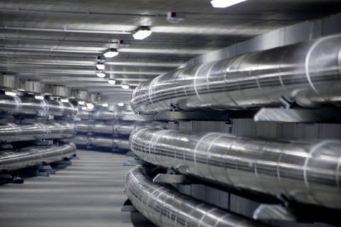
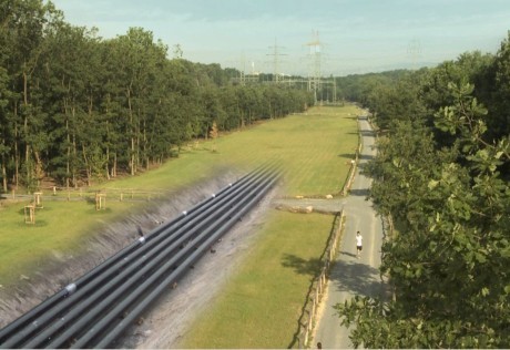
Figure 2: first picture: view into a tunnel with two GIL systems and elastic bending, Paulaner Munich; second picture: directly buried GIL at Kelsterbach, close to Frankfurt Airport
HVAC Substations
For HVAC substations, most current technologies will still be in use for the coming years even in the absence of major new technologies, e.g. breakers, busbars, disconnectors and power transformers.
Electric utilities have to face increasingly complex issues in a continually evolving business environment. In order to increase controllability and data gathering, additional, available technologies will increasingly be embedded in existing and future substations. They are grouped as follows:
- Power control devices: FACTS, phase-shifting transformers
- Monitoring devices and systems: PMU, WAMS, Synchrophasors
- Compensator: SVC, STATCOM
Some of these technologies are described below.
Phase Shifting Transformer
Phase shifting transformer (PST) is a mature technology, implemented by TSOs in Europe to control active power through preventive or curative strategies. The PST system provides a means to control power flow between two grids. PSTs do not increase the capacity of the lines themselves, but if some lines are overloaded while capacity is still available on others parallel to them, optimising the power flows with PSTs can increase the overall grid capacity.
In the future, the focus will be on enabling issues: the development of shared PST models by TSOs and standards should facilitate PST integration in transmission systems. In parallel, the development of cross-border power trade and the integration of renewable generation will increase the need for such a technology to be in operation.
Static VAR Compensators
A Static VAR Compensator (SVC) is a fast acting power electronic device used to dynamically control the voltage in a local area or at an interface point. It is a member of the family of equipment known as Flexible AC Transmission Systems (FACTS). Essentially SVCs and STATCOMs deliver a similar function using different power electronic technologies and methods.
The SVC provides variable inductive and capacitive reactive power using a combination of thyristor controlled reactors (TCR), thyristor switched reactor (TSR), and thyristor switched capacitors (TSC). These are connected to the AC network using a compensator transformer or via a transformer tertiary winding.
STATCOM
A Static Synchronous Compensator (STATCOM) is a fast acting device which can produce or consume reactive power, more quickly than with AC capacitor banks, reactors or SVCs. It is a FACTS technology, which may be used for example at an onshore interface point to achieve System Operator/Transmission Owner Code (STC) dynamic compliance between 0.95 power factor lag and 0.95 power factor lead. The design and faster response enables it to be used to actively filter harmonics and flicker to improve power quality. STATCOMs are voltage source converters (VSC) using IGBTs (Insulated Gate Bipolar Transistor) or IGCTs (Integrated Gate Commutated Thyristors). They can also incorporate static capacitors and reactors into their design but these are typically smaller in comparison with those required by Static VAR Compensators (SVC), and therefore have an overall smaller physical footprint.
WAMS, Synchrophasors and PMU
Power grids are expected to operate closer to their maximum capacity and on the other hand, there is an increased need for accurate and better monitoring of the network. The use of synchrophasors is a novel method for measuring and determining absolute phase relationship between phase quantities at different locations on power systems. Phasor measurements that occur at the same time are called “synchrophasors”.
A Phasor Measurement Unit (PMU) measures the electrical waves on an electricity grid to determine the health of the system. A PMU can be a dedicated device, or the PMU function can be incorporated into a protective relay or other device.
The main application of synchrophasors is in the field of system monitoring with Wide Area Monitoring Systems (WAMS). The interest is to use synchrophasors in order to obtain a precise view of the system and its limits. A more advanced application is to use synchrophasors as basis of new automatic protection systems, which can be local or Wide Area Protection Systems (WAPS). The main benefits of synchrophasors are for on-line monitoring, protection systems and off-line analysis.
PMU’s are used in WAMS by a large number of transmission system operators which have started exploring this technology and getting familiar with its use and functions.
HVDC Power Transmission
Introduction
Europe has been and remains a pioneer and an innovator in the field of HVDC since its modern re-invention in the second half of the 20th century. Multiple HVDC schemes have been designed and installed, mostly point-to-point schemes using submarine cables to exploit the sea crossings in Scandinavia, the British Isles, the Baltic Sea, the North Sea and the Mediterranean Sea. A limited number of back-to-back schemes have been built, the most recent being the 2 x 500MW link between Lithuania and Poland. There is only one working multi-terminal system in Europe, the Sardinia – Corsica – Italy (SACOI) link, although others are in construction (South – West, in Sweden and Caithness – Moray – Shetland, in the UK).
HVDC cable technology has been implemented for more than 60 years:
- Initially, Mass Impregnated (MI) cables were regarded as the preferred solution. Line Commutated Converters (LCC) were used, implying polarity reversal. Almost all of the schemes built in this period have used LCC technology
- In the 1990s, the development of Voltage Source Converter (VSC) technology was considered as an opportunity to introduce XLPE extruded insulation cables for HVDC applications in addition to MI cables. VSC has rapidly gained acceptance, such that it is now the predominant choice for HVDC schemes throughout Europe
The differences between these two technologies and hence an explanation for the rapid change from LCC to VSC schemes are discussed in the following sections.
Mass Impregnated HVDC Cables
Mass Impregnated (MI) HVDC cables are currently the most used cables for HVDC applications. Benefiting from more than 40 years of experience in service, with a proven high reliability, they can be provided by European manufacturers at voltages up to ±600 kV and 1800 A, which makes 2200 MW per bipole. Currently, this technology is mainly deployed for HVDC subsea applications.
Following evolution for MI HVDC cables includes:
- Increase in power (from 1560 to 2340 MW per bipole) and voltage (from 500 to 600 kV);
Thanks to progress, particularly the upgrading of service voltage, it will be possible to transmit a power of 1000 MW with a reduction of around 30% in the losses per bi-pole;
- An increase in water depth for submarine installations from around 1600 m to over 2500 m by 2050.
Extruded XLPE HVDC Cables
Polymeric HVDC cables are used mainly with VSC converters that enable power flow to reverse without polarity reversal. Up to now, this technology has been implemented up to ±320 kV with a capacity of 1000 MW for a symmetrical monopole. The basics for HVDC subsea cables are the same as those of HVDC underground cables except for mechanical features.
The following evolution of XLPE HVDC subsea and underground cables can be expected:
- Increase in voltages up to 550 kV;
- Increase in conductor size from 2500 to 3000 mm2, which is expected to result in a capacity exceeding 2 GW;
- Due to the increased voltage, the typical losses per circuit (2500 mm2 conductor rated at 1 GW per bipole) are expected to drop from 42 W/m (today) to 14 W/m (by 2050);
- Reduction of losses per circuit (bipole) of approximately 40% when XLPE HVDC cable will be operated at maximum power;
- For subsea cables, the laying depth should reach more than 2500 m by 2050
HVDC underground and submarine examples include:
RTE / RED INELFE HVDC+/- 320kV Interconnector France-Spain: Total length 65 km underground cable, of which 8.5 km is through a tunnel underneath the Pyrenees, transmission capacity 2 GW, XLPE cable
TenneT Nordlink, HVDC +/- 500 kV Interconnector Norway – Germany: Total length 623 km of which 516 km is offshore submarine cable, 53 km HVDC overhead line (Norway) and 54 km HVDC underground cable (Germany), transmission capacity 1,4 GW, MI cable
TenneT Borwin 2, HVDC +/- 300 kV Connector, Germany: 75 km land cable, 125 km submarine cable, transmission capacity: 800 MW, XLPE cable
Line Commutated Converter (LCC) technology
HVDC stations using LCC technology have been widely implemented throughout Europe and the world since the 1960’s, for both OHL and cable applications. The technology is based on the use of high power thyristors, which provide the switching between the HVAC and HVDC systems. The technology is widely used for point to point, or back to back links between asynchronous networks. It can also be implemented as an embedded link within a synchronous network.
Following many years of development, thyristor devices are able to operate at voltages up to 8.5kV and switch DC currents of up to 5000A. This has allowed LCC schemes to be installed up to 7200MW and ±800kV, although to date such ratings are only required in China, India and Brazil. In Europe the largest LCC scheme, currently under construction, is rated at 2200MW at ±600kV (Western Link in the UK). A key feature of this thyristor based technology is its short time overload capability, allowing schemes to have significant (1.3 – 1.5pu) levels for useful times (1 – 3s) to support the wider AC network.
LCC technology is highly efficient, with a total operating power loss in a converter station of typically 0.7 – 0.8% of the scheme rating.
Voltage Source Converter (VSC) technology
HVDC stations using VSC technology have been in service since 1999. The technology is based on the use of Insulated Gate Bipolar Transistors (IGBT), which provide the switching between HVAC and HVDC systems. To date all applications, with one exception, use sub-sea or underground cables. In addition to point to point links and back to back links, the technology is also suitable for developing multi-terminal systems. The first of these are in operation (in China) and others are in construction (in Europe).
In comparison with LCC technology, VSC is a relatively less mature technology, using IGBT devices rated up to 4.5kV and 2000A. The largest scheme in service is the 2 x 1000MW ±320kV INELFE project (France – Spain) and the highest voltage is on the 700MW Skagerrak Pole 4 project at 500kV (Norway – Denmark). The North Seas Network (NSN) project now under construction between the UK and Norway will operate as a bi-pole at 1400MW and ±525kV. Although power and voltage ratings have risen dramatically in recent years, the overload capability of VSC technology still remains low, limited by the capability of the IGBT devices.
The operating losses of VSC technology have decreased dramatically in recent years to reach about 1% per converter station. Although still higher than LCC technology, the ancillary services available from VSC converter stations, such as reactive power control, voltage control, frequency control and black start has made VSC the preferred choice for all new HVDC stations in Europe.
DC Gas insulated lines
DC gas-insulated technology was first established in the 1970s with several development projects in USA, Sweden and Germany. The focus of these developments was to reduce the space for HV DC converter stations and to provide powerful underground transmission systems. In parallel DC GIL for 500kV are renewed and being available from 2017 on. Systems are reduced in diameter ~by half, compared to first applications. The designs are suitable for the transmission of high power (5000A DC / 5GW) over long distances. Modern DC GIL systems are designed to harmonize beside half-bridge VSC and LCC also with modern VSC full bridge inverter. DC-CTL can directly interface with DC GIS as well as with OHLs via air bushings.
HVAC / HVDC Hybrid System
HVAC / HVDC system Interaction
The HVDC technologies have been gradually integrated to the existing pan-European HVAC system. With the estimation of TYNDP, over 25,000 km of HVDC transmission lines will be built and operated in parallel with over 300,000 km HVAC transmission lines. HVAC / HVDC interaction will be a key feature in the coming years for system operation, development and maintenance. The HVAC network, which needs to be able to supply or evacuate the power of the HVDC link, may require system reinforcement. Under certain contingency conditions on the HVAC network, automatic curtailment of the HVDC link power may be required due to thermal reasons or to maintain system stability. Issues related to the active control of reactive power interchange have made VSC technology the preferred and sometimes the only choice for many schemes. In networks with high levels of background harmonic distortion, the low levels of distortion achieved by VSC converters can make them an attractive solution.
Hybrid HVAC / HVDC Overhead Lines1
An upgrade of the existing transmission lines from low voltages (110kV, 150 kV or 220 kV) to 400 kV level can relieve some level of congestion but not totally, since this grid will reach its capacity limits and, due to the extensive loading, stability problems cannot be excluded. Therefore an overlay HVDC grid is under consideration.
Due to the lack of new transmission line corridors and public concerns about the erection of new transmission lines, increasing transmission capacity by converting one of the existing HVAC lines into 400 kV or 500 kV HVDC circuits is of interest.
Some examples of HVAC / HVDC hybrid lines are presented in Figure 3 and Figure 4. In Figure 3 double-circuit lines are shown at which one HVAC circuit is converted to HVDC. Figure 4 represents a four-circuit line with two circuits on each side of the tower. On one side of the tower an HVAC circuit is converted to HVDC.
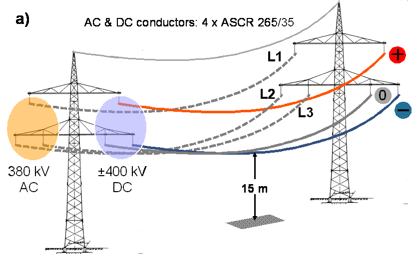
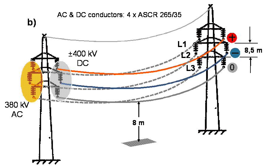 Figure 3: DOUBLE-CIRCUIT LINE, AC AND DC SYSTEM A) TRIANGULAR; B) SEMI-VERTICAL
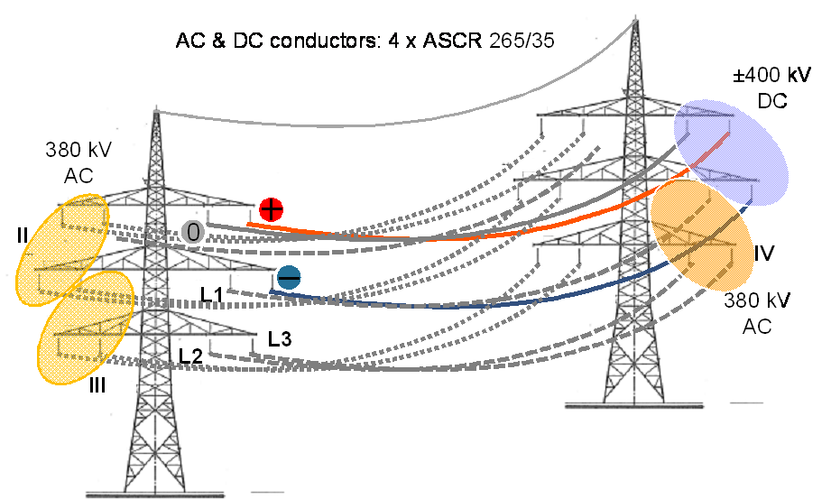 Figure 4: FOUR-CIRCUIT LINE, ONE AC CIRCUIT CONVERTED TO DC
One major issue of HVAC / HVDC hybrid lines is the coupling between HVAC and HVDC circuits. For this, one has to consider capacitive, inductive and resistive coupling.
As known from investigations on model test arrangements and on a test line, the limit values of the above mentioned quantities given in the CIGRE TB 388 recommendation are covered for 400 kV HVDC, if the conductor surface voltage gradient of 28.8 kV/cm is not exceeded and the minimum distance to earth of the HVDC conductor is not less than 15 m.
There are no explicit standards available for such HVAC / HVDC hybrid lines. However, for consideration of the mechanical stability of hybrid line towers the standard EN 50341 for HVAC lines which corresponds to IEC 60826 can be applied. For new hybrid lines the standard for erection of HVAC lines is applicable, since the HVDC circuit will be equipped with the same type of towers and the same components as the HVAC circuit. For conversion of existing HVAC circuits into HVDC circuits the HVAC standard can also be applied, as long as the mechanical loadings are corresponding. Actually the conductors remain unchanged when a conversion of an HVAC circuit into a HVDC circuit is planned. In principal, the weight of the insulators including the fittings will be smaller or the same at most compared to the previously installed porcelain or glass cap and pin insulators due to the application of composite insulators. In this way the stress at the suspension point is the same.
The probability of faults on the HVDC lines, e.g. due to lightning strikes or polluted insulators, will require solutions which can clear the fault and auto-reclose in a similar manner to HVAC systems. This may require the use of more expensive VSC converter solutions, or the use of large and expensive DC circuit breakers. The overload capacity of the HVDC converters under N-1 operating conditions will also require careful consideration. The short-term overload capability of LCC technology may be suitable for such conditions, but VSC technology has very limited overload capability. To maintain some margin for N-1operation it may be necessary to over-rate VSC converters, which would allow the lines to be operated above their thermal rating.
Summary Table of Technology Availability
With expert view and development on the market, the availability of different technologies are given in Table 1. The judgement is done with a time interval of five years (2020, 2025 and 2030). The report uses the National Grid Electricity Ten Year Statement 2015 as an orientation to indicate the level of availability:
Table 1: Summary table of availability of different technologies
| Technologies | Technology Availability | ||
|---|---|---|---|
| 2020 | 2025 | 2030 | |
| Overhead lines | |||
| ACSS | |||
| ACCC | |||
| ACCR | |||
| Real Time Thermal Rating | |||
| HVAC cables | |||
| Onshore cable technology (upto 550 kV) | |||
| Offshore cable technology (upto 550 kV) | |||
| Onshore cable technology (upto 550 kV) | |||
| Gas insulated lines | |||
| HVAC Substation | |||
| Phase Shifting Transformer | |||
| Static VAR Compensators | |||
| STATCOM | |||
| WAMS | |||
| PMU | |||
| HVDC Power Transmission | |||
| Mass Impregnated HVDC Cables, ±600 kV | |||
| Extruded HVDC Cables, ±320 kV | |||
| Extruded HVDC Cables, ±600 kV | potentially in service subject to contract | ||
| Gas insulated lines, 525kV | |||
| Line Commutated Converter (LCC) | |||
| 7200MW, ±800kV (OHL) | |||
| 2200MW, ±600kV (MI cable) | |||
| Voltage Source Converter (VSC) | |||
| 1000MW, ±320kV (XLPE cable) | |||
| 1400MW, ±525kV (XLPE cable) | |||
| 2500MW, ±600kV (XLPE cable) | |||
| HVAC / HVDC Hybrid overhead lines | potentially in service subject to contract | ||
Abbreviations
ACCC Aluminum Conductor Composite Core
ACCR Aluminum Conductor Composite Reinforced
ACSR Aluminium Conductor Steel Reinforced
ACSS Aluminum Conductor Steel Supported
CIGRE International Council on Large Electric Systems
GIL Gas Insulated Line
HTC High Temperature Conductor
HVAC High Voltage Alternating Current
HVDC High Voltage Direct Current
IEC International Electric Commission
IGBT Insulated Gate Bipolar Transistors
LCC Line Commutated Converters
MI Mass Impregnated
MVA Mega Volt Ampere – Apparent power unit
MVAR Mega Var – Reactive power unit
MW Mega Watt – active power unit
OHL Overhead Lines
VSC Voltage Source Converters
FACTS Flexible Alternating Current Transmission Systems
PST Phase Shifting Transformer
RTTR Real Time Thermal Rating
PMU Phasor Measurement Unit
SVC Static VAR Compensator
STATCOM STATic Syncrhonous COMpensator
XLPE Cross Linked Polyethylene Insulation
WAM Wide Area Monitoring
B Rusek, K Vennemann, J Velasquez, K Kleinkarte, C Heising and V Staudt, “Special requirements regarding VSC converters for operation of hybrid AC/DC overhead lines”, paper B4-108, CIGRE conference, Paris, France. 2014 ↩